Post
Progressing Research: Bugs and Mistakes
Recently I’ve made some progress on developing a new IR communication board SwarmB3 for my research interests in swarm robotics. It is quite an interesting journey, solving bugs and mistakes from electronics upwards into software. Because of the variety of my work commitments, I currently feel like I am speed-running a full cycle of prototyping to research outcomes, targeting eventual publication. I would like to try and get a paper submitted by September 2026.
The below photo shows some hardware hacks to try and get things working. The board on the left is a new board I am designing for teaching in the new academic year. For this board, I discovered that 3 of the GPIO weren’t electronically connected to the sensors. I discovered this the hard way, attempting to read my sensors in software was returning values that didn’t change. Locating the error came down to using the diode test function on a digital multimeter between the PCB component pads.
When I reviewed my electronic schematic in KiCad, I found a small box indicator rather than a dot indicator, meaning that the electronic connection was not defined. Even though the fix was a few mouse-clicks, I had to wait for another round of PCB production, shipping and delivery. However, I also discovered that one of the GPIO I wanted to use does not work if the WiFi module is enabled - so my first mistake (not having GPIO connected) became useful in allowing me to test other GPIO to read the sensors.
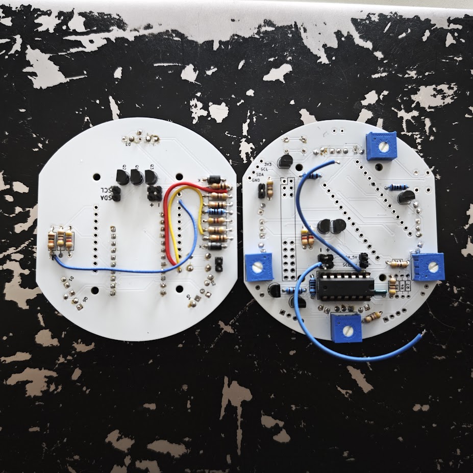
On the right is an earlier version of my new communication board. My hardware bugs and mistakes here were much more painful to resolve, probably taking a couple of days of cummulative time. I’m using an Adafruit ItsyBitsy M4 (SAMD51 device) because it can be configured to operate 4 independent UART interfaces. My first hardware bug was quite confounding. I use an AND gate to combine transmission data with a carrier signal. However, when I measured the output of the AND gate via an oscilloscope the logic was crazy. To cut a long story short, it turned out that the PCB had an isolated ground plane, so the AND gate wasn’t correctly grounded.
My second bug was much more annoying, and I chased my own tail for a while. Reading the datasheet for the SAMD51, I found that it is possible to invert the transmission logic and so designed my circuit board on this premise. However, it turned out it wasn’t that simple. Setting the UART to invert only inverted the data logic levels, and not the idle logic. For my IR communication board, this has the adverse effect that a high idle state means that the IR LEDs are always on, saturating the environment. I tried many different ways in software to find a different configuration, or to pull the GPIO line low when idle. However, a small transient glitch when handing over GPIO control back to UART seemed to render this approach ineffective on the receiver side - it would always lock on to the datastream incorrectly.
Eventually, almost as a result of pure frustration, I went back to a breadboard and wired up a logic inverter IC instead. This worked (of course). Sometimes a hardware fix is easier than a software fix. Updating the PCB design to include an inverter IC wasn’t too bad, and again - the wait for manufacture, shipping and delivery. When I received the next version, it turns out I made a similar mistake again - an isolated ground plane. I had checked for this multiple times, but it still escaped me. Fortunately, this time I was quick to check all the relevant connections and re-discover this problem.
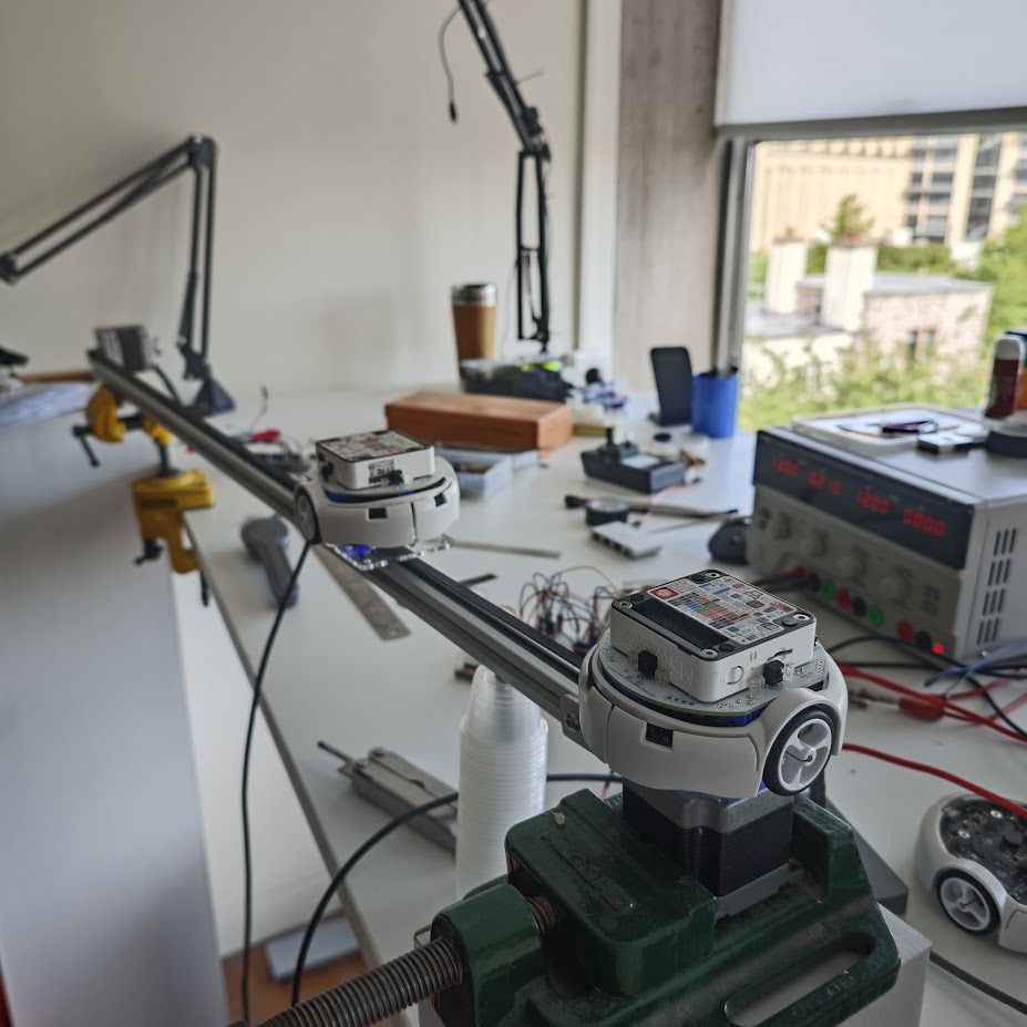
I’ve got to the stage where I am now taking measurements of the communication board in application. In December 2024 I took similar measurements of the previous version of the communication board Swarm-B2. The fact that it was 16 months ago since I last had time to work on my communication boards feeds into my current speed-running attempt. When I took those measurements, I placed two robots in different positions manually (by hand). It took a long time to do. This time, I’ve managed to assemble the pictured test rig above. This test rig is using two stepper motors to automatically and sequentially move robots into a variety of exact positions. I’m very pleased with how this is working, and it is very satisfying to press “go” and come back later. This stage of my speed-running attempt is during an office move at work.
When I produce the plots I have been able to observe some unexpected outcomes and I have to ask myself if this is something inherent, or whether it is emerging from my hardware or software design. For example, in an early plot I could see a clear area of non-transmission between two LEDs. My first reaction was surprise - I thought that I had physically placed the LEDs at just the right angle to create this gap. I considered going back to the PCB design to fix it. However, with some further thought and inspection of data, it turned out to be the effect of signal interference between LEDs. As I mentioned previously, the board has independent UART interfaces and I wasn’t managing to synchronise them successfully. It is quite fun to go back to data and the code and find the source of the problem - and then verify the fix with subsequent measurements. So far, I’ve implemented two fixes, one improving on the other.
Overall, I am finding it very satisfying to develop something from electronics upwards, from scratch, on my own. I feel that I am continuing to learn a lot. It is also very satisfying to be presented with an issue, and to be able to think across all levels of the system. Because of the painful bugs at the hardware level, I feel quite intimately familiar with the low level registers. I also had to do a major re-write of the firmware to remove some blocking code. In combination, it becomes interesting when a problem occurs, rather than frustrating - and I think that is because of familiarity with the whole of it. I imagine that this isn’t a situation that many are in. Typically work is conducted in teams, and we inherit systems or products to maintain or improve.